Getting the Phenoptix MeArm to work with ScratchGPIO

tl:dr

Buy, or build your own robotic arm from the plans available from phenoptix.  Connect it to a Pi using an Adafruit I2C servo controller board.  Control it using ScratchGPIO.  Get creative.  This is perfect for KS2 or KS3 students who want a build challenge, but aren’t quite ready for the challenge of coding the robot control in python.

Background

I bought a MeArm from Phenoptix before the Christmas break, as my STEM club kids had wanted to build a Mars Rover style robot with a robotic arm.  I thought I’d start small and work my way up to building my own  so I bought a retail kit from the phenoptix website after being really impressed with the V3 at the Poole Raspberry Pi Jam 2014.

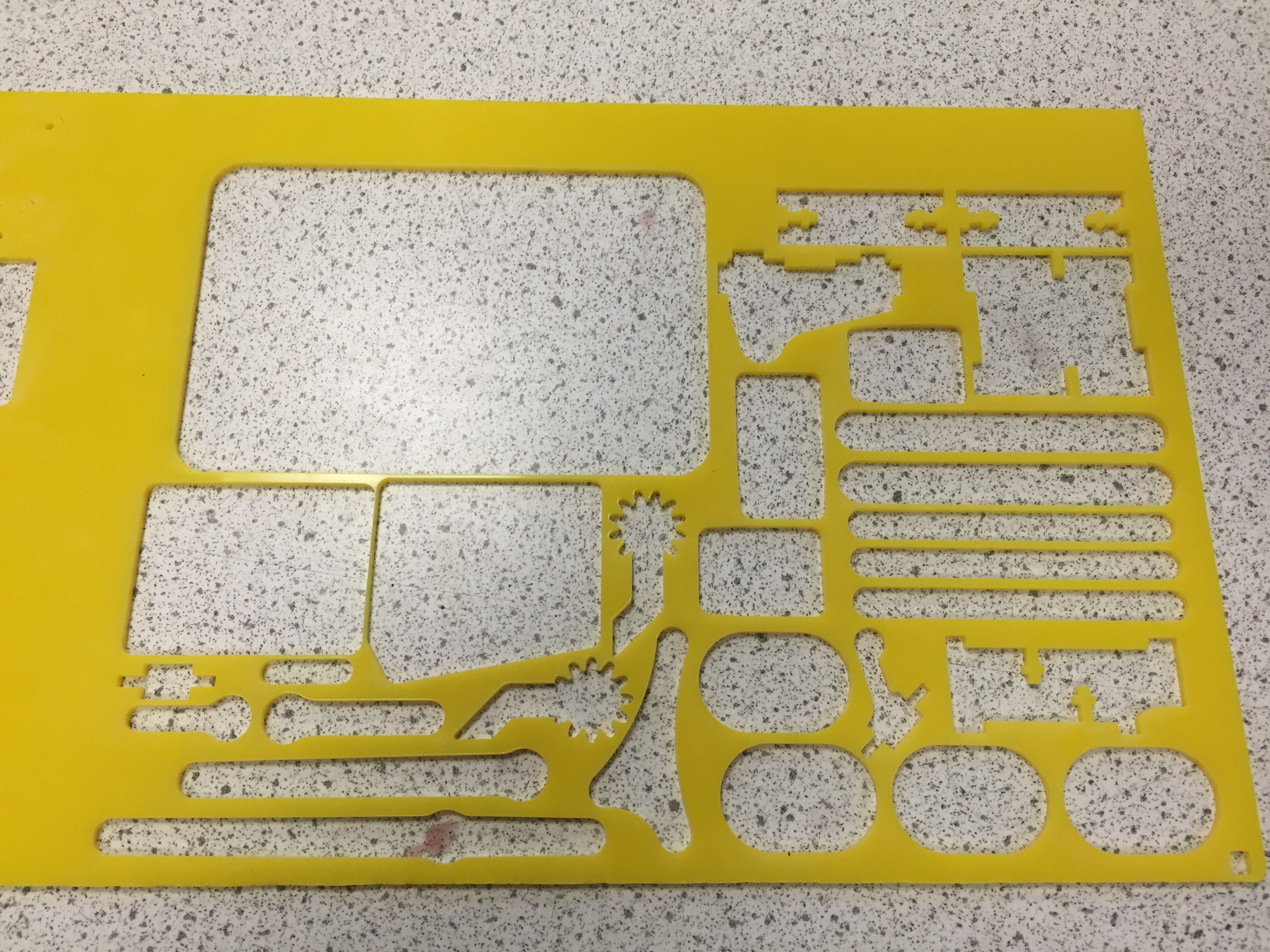
The kit is sold by Phenoptix (www.makersify.com) and comes with everything needed to build the robot, including laser cut acrylic parts, M3 nuts and bolts for fixing, and 4x 9g Turnigy servo motors.   They also entered the design into the Hackaday I/O contest, and open sourced the hardware so you can roll your own if you need to.    This makes it an amazing choice for school STEM projects if your school has access to a laser cutter or a 3D printer, as you can make the robot for less than £20 quid and a dig around in the parts bin.  Controlling the robot is left up to you: There are build instructions for Arduino, Pi, and Beaglebone (and presumably ninja skills with 555 timers and pots) as the control methods.  The code for all these has been hosted on gitub.

Our own laser-cut MeArm parts, as shared on Thingiverse.
Our own laser-cut MeArm parts (well, they’ve been removed from the acrylic), as shared by Ben on Thingiverse.
The build was moderately difficult for KS3/KS4 students, and was not helped by the sometimes obtuse instructions on www.instructables.com.  The Stem club were going to try and document a clearer build – I think the instructions could be done in a different colour acrylic to make it clearer, or perhaps add some 3D or wireframe instructions like an IKEA flatpack build! One of our improvements was to add engraved numbers to adjoining edges, so 2 fits with 2, 5 with 5 etc.  But then again, solving problems is part of the whole STEM process!

The Build

My initial kit had the incorrect number of parts, so the build stalled about 2/3 of the way through but a quick email to the website meant they dispatched replacement parts in about 4 days.  It’s really important to get the initial positions of the servos correct in the build, as it can have two consequences:

  • Having to disassemble the robot to correct the servo position in order to get the full range of movement. (A pain)
  •  If the base servo is misaligned, the robot can end up pushing against the supports and burning out your servos. The claw servo can also burn out easily if you haven’t set limits in software and misaligned the servo before assembly.
    Robots building robots. Skynet!
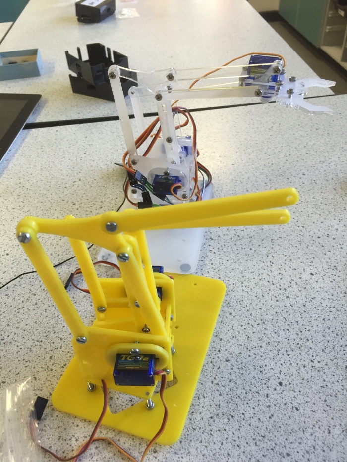
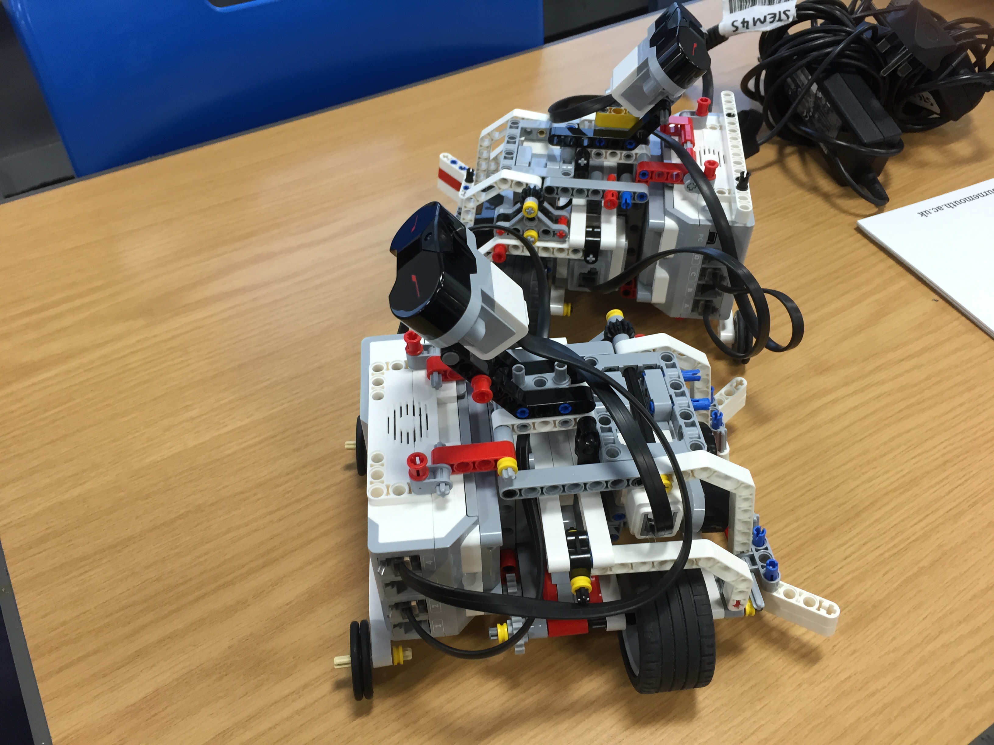
    .Retail Kit meArm is in the background.  Our own version is in the foreground. I watched them build it without setting the servo positions correctly and kept quiet.    Then they worked it out for themselves, and disassembled, reset and rebuilt without my help!

Once assembled, the robot looks pretty awesome  but  the robot won’t be able to move without precisely timed PWM signals generated from a Pi, Arduino, Beaglebone or a servo controller unit.  These have to be precisely timed, and require a PWM pin, +5 V and ground for each servo.

Connections to the GPIO

This how-to is for a Raspberry Pi Model B or B+ (not a Pi 2) , using Adafruit’s 16 channel servo controller board, Scratch GPIO 7.

I decided to use the Adafruit 16 channel servo controller. It works over i2C, and so only requires 4 pins from the GPIO.  You will have to enable i2C on your Pi first, by following the tutorial online at Adafruit Learning Centre

1. Assemble the Adafruit board by soldering in the header pins

2. Enable i2C on your pi by following the instructions at the Adafruit Learning Centre.  This is just editing a config file and then rebooting  down the Pi

3.Attach the breakout pins on the Adafruit board pins to the correct GPIO pins as shown below.

The Pins we need are GPIO 1 (3v3), GPIO 3 (SDA), GPIO 5 (SCL) and GPIO 6 (GND)
This picture is from a B+ GPIO.

Make sure that the Pi is turned off before attaching pins to the controller board!

VCC is attached to 3V3 (GPIO 1 )       This provides the voltage for the controller chip at 3V.

Gnd is attached to Gnd (GPIO 6 )         This provides a ground voltage for the controller chip at 0V

SDA is attached to SDA  (GPIO3 )                  This pin is the Serial Data pin, where all of the PWM signals are pushed to the different servos

SCL is attached to SCL (GPIO5 )         This pin is the Serial Clock pin, where the timed pulses for i2C master-slave communication are generated.

The correct pins are on the header on the left hand side: The GND, SDA, SCL, VCC pins are the ones we want.
and you should get output that it has detected your device (mine was 0x40)

Connecting the servos to the board.

Connect each servo to the board correctly:

Make sure that the Black wire is connected to ground, The red wire to V+, and the White wire to PWM.

I connected the servos to the board as follows:

  • Base servo: Channel 0
  • ‘Shoulder’ servo: Channel 1
  • ‘Elbow’ servo: Channel 2
  • ‘Gripper’ servo: Channel 3

I usually have a whole bunch of female-female header leads for experiments with Raspberry Pis, and then I use solid jumper leads to connect these to the servo leads.  You should thread the leads through the centre of the arm to keep the leads tidy, and to minimise snagging whilst the robot is moving.  You’ll need to extend the servo leads of the micro servos in order to prevent any tension whilst the robot is in motion.  I’ve got 20cm jumper leads bought on Amazon, and can highly recommend them for STEM projects.

The Adafruit 16channel 12bit i2c board, allows the Pi to control the 4 servos using i2c over the GPIO.  You need to use an external 5V power source to power this board, otherwise the Pi will brown out whenever the servos are moving.  You can damage your Pi if you try to drive 4 servos with the GPIO.  I used an external bench power supply to make sure the servos got  a constant voltage supply.

Make sure that you connect the servos to the Adafruit board, the Adafruit board to the GPIO and the External Supply to the Adafruit board whilst the Pi is powered down.    Check, check and check all your connections again.  The GPIO can be a fickle beast, and connecting it incorrectly can damage the Pi.  Be nice to your Pi.

Once you reboot your Pi, you should see the adafruit board will light up, and you can check that the Pi can see the i2C device with

 sudo i2cdetect

Connecting the Adafruit Servo Board to Scratch GPIO.

Install ScratchGPIO on the pi using

 wget http://bit.ly/1wxrqdp -O isgh7.sh

followed by

sudo bash isgh7.sh

ScratchGPIO7 should then be installed.  If you don’t get a link on the desktop, you might need to dig around in /etc/ to locate the scratchGPIO7.sh file.

Start ScratchGPIO.  The program should automagically detect the i2c device if it can be seen using the i2cdetect command.

Set up some variables:

AdaServo0       – This is channel 0, the base servo, and should only be sent values ranging from -90 to 90

AdaServo1        -This is channel 1, the shoulder servo, and should only be sent values ranging from 70 to 0

AdaServo2        -This is channel 2, the ‘elbow’ servo, and should only be sent values ranging from 20 to 70

AdaServo3        -This is channel 3, the gripper servo, and should only be sent values from 0 to 30.

These values are all assuming that you have assembled the arm according to instructions.  You might find that your ranges are slightly different.

You can choose to increment the values of the variables by using the arrow keys, or you might create a generator script which will automatically scan through the values for each variable.   we had a ‘panic’ function that set the robot to a home state with a single button press if things got hairy!

Here’s a video of it in action:

Be careful not to exceed the maximum values for the servos.  The 9g servos have relatively weak plastic gear trains, and can strip their gears easily!

We’ll share our scratch code, and will post our python code as soon as we can get coding again.

Polargraph is go!

For Science and Engineering week, I thought it would be inspiring to make a giant Polargraph machine that would be left all day to draw at school.  They occupy a perfect space at the intersection of art, maths and technology.

The penrose triangle.  I drew this using vector drawing mode, and generated the file using StippleGen2 from EvilMadScientist labs.  <3
The penrose triangle. I drew this using vector drawing mode, and generated the file using StippleGen2 from EvilMadScientist labs. ❤

What is a Polargraph?

A polargraph is a line drawing machine that uses two fixed stepper motors to move a hanging gondola that holds the pen.  The machine usually draws pictures using a continuous line.

Why is it called a polargraph?

The machine uses a polar co-ordinate system to calculate where the pen is, and how far to move the motors in order to draw lines. (It can convert polar co-ordinates to Cartesian x-y co-ordinates)

How does it work?

The polargraph controller takes a .png, .gif or .jpg image as the input, and decides on the brightness of different areas in a grid. If an area is dark, then the machine tells the arduino to signal to the motors  to put the pen lines close together, and produce a dark shaded pixel. .  If an area is light then the machine tells the motors to put the lines further apart.

What can it draw?

It can draw any bitmap image that it is given.  It works best with high-contrast images.    It is quite versatile and can draw in a variety of ways – It can scribble, it can draw circles, or it can build pictures up in squiggles or perfect square waves.   The curved bands are due to the way that the motor instructions are generated, and which point is fixed in the picture. It can draw vector files directly, as they are path-based images.

How did I build it? 

I followed the truly incredible instructable form Sandy Noble at instructables.  It’s one of the best that I’ve ever followed – The instructions are clear, the walkthroughs are detailed to just the right level, he links to all the influences he used for the project, and it produces amazing results.

Polargraph Community

Although Sandy  has been inspired by others, including Der Kritzler machine and others he really has nurtured a community around polargraphs and V-plotters through a great forum, and excellent communication with customers or interested people.  He has also innovated in the area of v-plotters and really enabled a community to move forward by open-sourcing his designs and software.   It’s entirely possible to buy ready-made plotters from the polargraph store, but I really wanted to roll my own and follow the instructable.

Mark 1 – (prototype) 

I built a comedy home version at first, with the stepper motors velcroed onto the top of the board directly.  This had an advantage where there a bit of play in this mounting system, and it absorbed some of the resonance in the cables.

I built it using a an arduino uno (legit!), and an Adafruit motor shield V1 clone from ebay (only because the real one isn’t made anymore).   I don’t have access to a 3D printer, or a laser-cutter at home.   so I tried to make a home-grown solution to the gondola, but ended up buying a kit from the polargraph store.

Problems that I had while building the prototype machine and how I fixed them:

1. Motors turned backwards – Answer steppers wired in reverse. This was apparent as I moved my arduino from the front of the machine to the rear between revisions!

2. Gondola moved off edge of page when drawing – hadn’t set machine size before starting and uploaded to the arduino.  This is a really important stage that has to be done every time, or saved into the default_properties config file.

3. Pen would slip in picture – My counterweights were hitting the floor as the strings were too long.  This was solved by shortening the blind cables, but I think in future I will try and use a pulley system to stop the cables vibrating and resonating.

4. Stepper Motors were getting crazy hot -I stole some heatsinks from a PC graphics cards and  added small heatsinks to both the motor driver ICs on the motor board, and to the top of the steppers.  I also drove them at lower voltage and reduced the max speed.  This solved the problem nicely.

5. Pen was lifting from the paper causing incomplete pictures – I worked out a technique to get the paper as flat as possible in terms of using masking tape.  In future, I’ll use low-tack spray mount to get the paper to attach flat to the board, and then mask the outsides.

6. Servo failing to lift.  –  It took me a while to find this one out.  My servo was loose from the gondola, and was failing to lift in certain parts of the image.  This is a major headache if your machine has spent 6 hours drawing a flawless image, only for the servo to unstick, and then draw a line across the middle of the image.  Solution – Use a stronger adhesive or change the gondola.

Pl
Comedy Mk1 version.  Gaffer tape all round, counterweights made from bags of coins, stepper motors held with gaffer and velcro.  Amazing that it could still draw, all things considered.  This was my second ever image.

V1 It took me about 8 hours total to construct, and more importantly about 8 hours to troubleshoot.  Getting to know the software is really important.  Once I’d worked out what worked and what didn’t (and how to get the best out of my pens, paper and machine, I set my sights on the largest machine that I could build and transport.

Polargraph Mark II. 

It took about 4 hours to build, including a hinged A-frame so that I can change the angle of the board, and prop it up in public spaces without too much hassle.

The machine measures 1100 mm x 1800mm (The largest board I could fit into my car).

The only significant changes I made were that the machine size is effectively tripled, the electronics are all hidden at the back (a bit of a shame for a public machine I thought, but it would reduce tinkering / breakage – I might make a perspex enclosure for all the goodies), and I drilled a 12mm hole centre bottom in the board to run the servo cable hrough from the bottom.  This serves to pull the gondola parallel to the board.

Subjects

Portraits seem to be the most popular polargraph subjects, as they are universally recognisable, and we have a significant amount of subconscious brainpower dedicated to face recognition.  I tried to go for a couple of portraits, but also tried to get kids talking about science, maths, art and technology through the pictures.

I’ve been plotting various famous scientists, impossible shapes, anatomy pictures and other random pieces for the foyer at school.

Madame Curie.  The picture looks a bit tatty towards the bottom left: The paper was not sitting flat, and the Pen got clogged with paper fibres.
Madame Curie. The picture looks a bit tatty towards the bottom left: The paper was not sitting flat, and the Pen got clogged with paper fibres.  I still love the detail in the top of the image. I’d like to repeat this one under optimum conditions.  Draw time: 11h!

Reception

Impossible shapes - Part 2.   I used an image, then used inkscape to trace vectors.  This .svg file was exported to the polargraph and then drawn.
Impossible shapes – Part 2. I used an image, then used inkscape to trace vectors. This .svg file was exported to the polargraph and then drawn. Draw time: 35m

The machine was almost universally well received, especially for portraits of people.  It generates so many questions from curious students, and there seems to be a constant phalanx of children in front of it walking back and forth to try and make the more abstract images resolve with distance.     It’s one of the most pleasing builds in terms of satisfaction, as it produces such amazing works of Art.

My next project is to get the machine to run from a Raspberry Pi, and to try and emulate the amazing work of the blackstripes.nl or the gocupi projects (who are ‘inspired by’ Sandy Nobles work themselves).

I’ll add a time-lapse video as I have time to make a full-length one of a long drawing!.

MeArm update – Work in progress.

Here’s an update of what we’ve been up to in the last 4 weeks of STEM club.

Team MeArm.

We initially built the excellent MeArm from a phenoptix kit, priced £29.99. It’s a nice robot with 4 degrees of freedom, that can be controlled via Arduino, Rasberry Pi, Beaglebone etc.  We managed to get it working really nicely with a Raspberry Pi and ScratchGPIO, Simon Walter’s excellent version of Scratch for the Pi.   The challenge for the group is to control the arm using Python.  It was suggested to use a Wii Nunchuk, or perhaps a Microsoft Kinect, but early experiments have suggested that keyboard input is challenging enough!

Robots building robots.  Skynet!
Progress on our MeArm build. The kit version is in the background, and our JCB yellow in the foreground.  We’re about 2 weeks away from movement control!

Once the robot is mechanically sound, and the servo positions are set, then we should be able to connect it via I2C using the Adafruit 16 channel Servo I2C board.  Once this is done, then we’ll release the python geeks, and let them run wild with their programming and imagination.

Lego Mindstorms EV3 ping pong challenge

Bournemouth University’s STEM outreach program came to visit Purbeck School on Monday, and bought with them 15 Lego Mindstorms EV3 kits. The kits had been made into pre-assembled robots with a Large Servo motor for lateral movement, and a medium motor to lift the arm assembly.  They had ultrasound sensors for distance sensing, and an IR sensor for manual control via the IR Beacon.

The brief of the day was simple: Write code for a Robot to be able to play a game of Ping Pong against another robot.  The challenge turned out to require problem solving, mathematics,  iterating, collaboration, failure, resilience and sabotage.

Mean looking Ping-Pong robots.   Note the Ultrasound sensor at the front.  The whole paddle assembly flipped up when the motor was set to turn.
Mean looking Ping-Pong robots. Note the Ultrasound sensor at the front. The whole paddle assembly flipped up when the motor was set to turn.

The challenge was really well structured, with the students learning the basics of connecting, writing code blocks and downloading them to the brick, and within about 20 minutes of starting, most groups had control of the servo motors, and shortly afterwards, they were able to add another loop to their program to control the flipper.  They had to figure out the correct number of degrees to rotate the arm in order for an efficient flip! IMG_1784

The code challenges were well-thought out, and got the students to learn the rudiments of controlling the robot successfully by thinking about how far the robots had to move by setting rotation limits on the motors, and learning to use logic and loops to make the robots respond to the infrared remotes.  They had time to test the robots out in the test arena,  and make sure that the robots were responsive to input, and could also hit the ball with the paddle.  There was  a key trade-off between Power and Speed at which the paddle moved, that the students had to find to hit the sweet spot.

Customisation was also a large part of the day, with some groups recording audio samples, or drawing their own pictures, or playing short musical sequences at the press of a button.  3 groups had ‘entrance moves’ and intimidating aggressive moves.

Once the matches began, it became evident that there were issues with IR interference from other groups since the EV3 kits limit you to 4 channels, and even in a large room, there was significant crosstalk between the groups.  (There was also a good amount of comedy sabotage to be had).

Playing the great game.  Getting the ball off the end of the table gains you a point.  The IR beacon was used to control the robots.
Playing the great game. Getting the ball off the end of the table gains you a point. The IR beacon was used to control the robots.
A Match in progress.  The board shows the channel choices.  Teams had to reprogram their 'bots to change channels between games .
A Match in progress with teams that finished 2 and 3rd.

There were 20+ matches, the competetive element was very strong and the quality of the sport got much better as the day went on.  In particular, the single-member teams did particularly well, ranking in 3rd and 4th place even though they had no previous experience with the NXT-G programming environment.   There had to be an overall winner, and team Virginia Tech prevailed in the end.

IMG_1814
The winning team. Their robot’s unique skill was to shout ‘BANTER!’ during matches. It also played a nice jazzy arpeggio. They managed to overcome significant issues with controlling their robot.

We hope to be involved with Naomi and the STEM outreach team again.  The feedback was really positive from the students, and this would work really well with a younger cohort of students.

Building the Phenoptix mearm from scratch:Sourcing parts and cutting your own

Having already bought and assembled a MeArm kit from Makersify, I decided to use the open hardwire files from thingiverse to laser cut all the parts from 3mm Acrylic.

Thingiverse files.  If your DT department in school is as awesome as mine, they’ll show you how to use the cutter so you can plan and cut your own designs.


download the DXF file from thingiverse and start cutting
Laser cut parts from the DT department, hot off the cutting bed. JCB yellow is a nice touch

I had some trouble with the .dxf files running in 2D design, so I printed the design out on paper first and then did all of the measurements, comparing it to the real mearm that I built in order to make sure the scaling was perfect.  (If not, the servos won’t fit in the holes, and the bolts won’t self-tap)

I also cut a mountboard version for the students to see, and get to measure with vernier callipers to check the dimensions.  (It turned out it had scaled wrong vertically, and the test-print would never have assembled as all the circular holes were ellipses!)


IMG_1678
Parts arrived in the post, enough for 4 robots, but we’ve only enough acrylic for one at a time. 

In order to build the robot, you’ll need a bunch of M3 bolts, and some Turnigy 9g micro servos.  I picked up a load of servos cheap on ebay , at £11.99 for 4, which seems like a good deal.   (I would get a spare set, in case you burn the servos out during a build!)

I used namrick.co.uk to get small batches of the screws, as they were by far the best deal I could find in the UK, cheaper by about £25 than all other dealers.

IMG_1680


Once the students had done the inventory, they began to follow the assembly instructions, starting with the baseplate.  Here you can see that the longer M3 bolts are used like standoffs in the assembly.  You can also see the mounting holes to bolt on an arduino for controlling the servos.


We’ll keep you posted on the build as it happens, and then how to control it with scratch on the raspberry pi.