Getting the Phenoptix MeArm to work with ScratchGPIO

tl:dr

Buy, or build your own robotic arm from the plans available from phenoptix.  Connect it to a Pi using an Adafruit I2C servo controller board.  Control it using ScratchGPIO.  Get creative.  This is perfect for KS2 or KS3 students who want a build challenge, but aren’t quite ready for the challenge of coding the robot control in python.

Background

I bought a MeArm from Phenoptix before the Christmas break, as my STEM club kids had wanted to build a Mars Rover style robot with a robotic arm.  I thought I’d start small and work my way up to building my own  so I bought a retail kit from the phenoptix website after being really impressed with the V3 at the Poole Raspberry Pi Jam 2014.

The kit is sold by Phenoptix (www.makersify.com) and comes with everything needed to build the robot, including laser cut acrylic parts, M3 nuts and bolts for fixing, and 4x 9g Turnigy servo motors.   They also entered the design into the Hackaday I/O contest, and open sourced the hardware so you can roll your own if you need to.    This makes it an amazing choice for school STEM projects if your school has access to a laser cutter or a 3D printer, as you can make the robot for less than £20 quid and a dig around in the parts bin.  Controlling the robot is left up to you: There are build instructions for Arduino, Pi, and Beaglebone (and presumably ninja skills with 555 timers and pots) as the control methods.  The code for all these has been hosted on gitub.
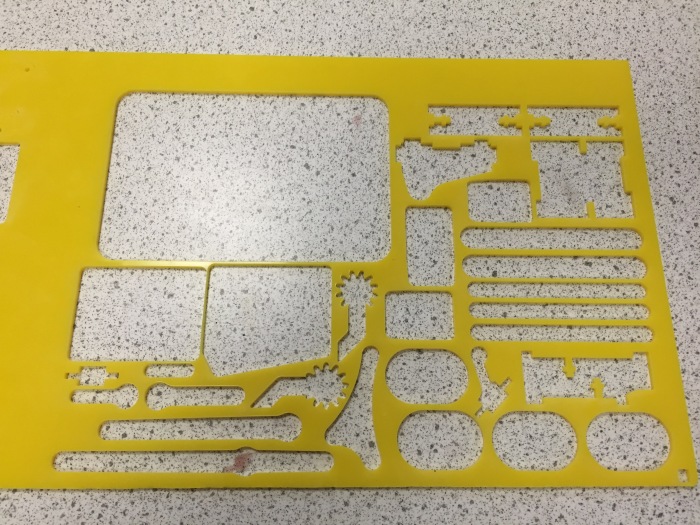
Our own laser-cut MeArm parts, as shared on Thingiverse.
Our own laser-cut MeArm parts (well, they’ve been removed from the acrylic), as shared by Ben on Thingiverse.
The build was moderately difficult for KS3/KS4 students, and was not helped by the sometimes obtuse instructions on www.instructables.com.  The Stem club were going to try and document a clearer build – I think the instructions could be done in a different colour acrylic to make it clearer, or perhaps add some 3D or wireframe instructions like an IKEA flatpack build! One of our improvements was to add engraved numbers to adjoining edges, so 2 fits with 2, 5 with 5 etc.  But then again, solving problems is part of the whole STEM process!

The Build

My initial kit had the incorrect number of parts, so the build stalled about 2/3 of the way through but a quick email to the website meant they dispatched replacement parts in about 4 days.  It’s really important to get the initial positions of the servos correct in the build, as it can have two consequences:

  • Having to disassemble the robot to correct the servo position in order to get the full range of movement. (A pain)
  •  If the base servo is misaligned, the robot can end up pushing against the supports and burning out your servos. The claw servo can also burn out easily if you haven’t set limits in software and misaligned the servo before assembly.
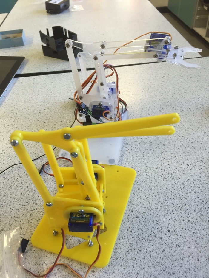
    Robots building robots. Skynet!
    .Retail Kit meArm is in the background.  Our own version is in the foreground. I watched them build it without setting the servo positions correctly and kept quiet.    Then they worked it out for themselves, and disassembled, reset and rebuilt without my help!

Once assembled, the robot looks pretty awesome  but  the robot won’t be able to move without precisely timed PWM signals generated from a Pi, Arduino, Beaglebone or a servo controller unit.  These have to be precisely timed, and require a PWM pin, +5 V and ground for each servo.

Connections to the GPIO

This how-to is for a Raspberry Pi Model B or B+ (not a Pi 2) , using Adafruit’s 16 channel servo controller board, Scratch GPIO 7.

I decided to use the Adafruit 16 channel servo controller. It works over i2C, and so only requires 4 pins from the GPIO.  You will have to enable i2C on your Pi first, by following the tutorial online at Adafruit Learning Centre

1. Assemble the Adafruit board by soldering in the header pins

2. Enable i2C on your pi by following the instructions at the Adafruit Learning Centre.  This is just editing a config file and then rebooting  down the Pi

3.Attach the breakout pins on the Adafruit board pins to the correct GPIO pins as shown below.

The Pins we need are GPIO 1 (3v3), GPIO 3 (SDA), GPIO 5 (SCL) and GPIO 6 (GND)
This picture is from a B+ GPIO.

Make sure that the Pi is turned off before attaching pins to the controller board!

VCC is attached to 3V3 (GPIO 1 )       This provides the voltage for the controller chip at 3V.

Gnd is attached to Gnd (GPIO 6 )         This provides a ground voltage for the controller chip at 0V

SDA is attached to SDA  (GPIO3 )                  This pin is the Serial Data pin, where all of the PWM signals are pushed to the different servos

SCL is attached to SCL (GPIO5 )         This pin is the Serial Clock pin, where the timed pulses for i2C master-slave communication are generated.

The correct pins are on the header on the left hand side: The GND, SDA, SCL, VCC pins are the ones we want.
and you should get output that it has detected your device (mine was 0x40)

Connecting the servos to the board.

Connect each servo to the board correctly:

Make sure that the Black wire is connected to ground, The red wire to V+, and the White wire to PWM.

I connected the servos to the board as follows:

  • Base servo: Channel 0
  • ‘Shoulder’ servo: Channel 1
  • ‘Elbow’ servo: Channel 2
  • ‘Gripper’ servo: Channel 3

I usually have a whole bunch of female-female header leads for experiments with Raspberry Pis, and then I use solid jumper leads to connect these to the servo leads.  You should thread the leads through the centre of the arm to keep the leads tidy, and to minimise snagging whilst the robot is moving.  You’ll need to extend the servo leads of the micro servos in order to prevent any tension whilst the robot is in motion.  I’ve got 20cm jumper leads bought on Amazon, and can highly recommend them for STEM projects.

The Adafruit 16channel 12bit i2c board, allows the Pi to control the 4 servos using i2c over the GPIO.  You need to use an external 5V power source to power this board, otherwise the Pi will brown out whenever the servos are moving.  You can damage your Pi if you try to drive 4 servos with the GPIO.  I used an external bench power supply to make sure the servos got  a constant voltage supply.

Make sure that you connect the servos to the Adafruit board, the Adafruit board to the GPIO and the External Supply to the Adafruit board whilst the Pi is powered down.    Check, check and check all your connections again.  The GPIO can be a fickle beast, and connecting it incorrectly can damage the Pi.  Be nice to your Pi.

Once you reboot your Pi, you should see the adafruit board will light up, and you can check that the Pi can see the i2C device with

 sudo i2cdetect

Connecting the Adafruit Servo Board to Scratch GPIO.

Install ScratchGPIO on the pi using

 wget http://bit.ly/1wxrqdp -O isgh7.sh

followed by

sudo bash isgh7.sh

ScratchGPIO7 should then be installed.  If you don’t get a link on the desktop, you might need to dig around in /etc/ to locate the scratchGPIO7.sh file.

Start ScratchGPIO.  The program should automagically detect the i2c device if it can be seen using the i2cdetect command.

Set up some variables:

AdaServo0       – This is channel 0, the base servo, and should only be sent values ranging from -90 to 90

AdaServo1        -This is channel 1, the shoulder servo, and should only be sent values ranging from 70 to 0

AdaServo2        -This is channel 2, the ‘elbow’ servo, and should only be sent values ranging from 20 to 70

AdaServo3        -This is channel 3, the gripper servo, and should only be sent values from 0 to 30.

These values are all assuming that you have assembled the arm according to instructions.  You might find that your ranges are slightly different.

You can choose to increment the values of the variables by using the arrow keys, or you might create a generator script which will automatically scan through the values for each variable.   we had a ‘panic’ function that set the robot to a home state with a single button press if things got hairy!

Here’s a video of it in action:

Be careful not to exceed the maximum values for the servos.  The 9g servos have relatively weak plastic gear trains, and can strip their gears easily!

We’ll share our scratch code, and will post our python code as soon as we can get coding again.

Microscopy – with added Pi

tl:dr :  I hacked open an intel QX3 toy microscope, replaced the crummy sensor with a Picamera, installed RPI_cam_web_interface on it and now have a wireless electronic microscope that you can control using a web interface.  It’s a great little teaching tool, and the camera can live with the microscope permanently, the Pi can be detached and used for other projects.

An intel QX3 microscope with a Raspberry Pi camera inside.  The Model B is mounted on top temporarily whilst I work on fitting an A+ inside the microscope body.
An intel QX3 microscope with a Raspberry Pi camera inside. The Model B is mounted on top temporarily whilst I work on fitting an A+ inside the microscope body.

Background: When the education pyramid for my county was collapsed into two tiers (Primary and Secondary only-  Middle schools were closed down), some of the science equipment was redistributed to other schools.  We got a bunch of the Intel Qx3 Mattel microscopes, which were ‘legacy equipment’, and hadn’t been used in years (sneeze alert).    I saw these sad microscopes and thought they could be revitalised with some ‘Pi inside'(TM) Back when they were released, they boasted fairly good specifications, including 10, 60 and 200x optical magnigfication, USB connectivity, CCD sensor capable of native res of 320×240, and incandescent illuminators above and below the stage.  They are great toy microscopes, and work well for the price, although the drivers haven’t been updated for Windows in years, and the software really only works reliably with XP.  This also means that if you do get an old XP box/laptop you have to use the heinous digital blue software bundled with the camera, which stinks of bloat, and wacky menus.  Getting it functioning: Mac OS X has a working solution with macam, but doesn’t allow direct control of the illuminators, and my school doesn’t have any OS X machines to hand. There is a solution for Linux machines that works as described in this excellent blog post here.  Since it works on a linux distro, and video4linux  identifies the camera as a gspca (CPiA) webcam, it should work on a Pi, since V4L is baked into the kernel of Debian. There is a great blog post here detailed how to get it working with Camorama. Naturally, I plugged it straight into a Pi via usb and managed to get it working in X using camorama using the following commands.

sudo apt-get update

sudo apt-get upgrade

sudo apt-get install v4l2 camorama mplayer ffmpeg

On running camorama, It worked, but it was really disappointing.  The res was low, the framerate from the webcam was sucky, the sensor had a huge amount of noise present and it crashed after about 2 minutes every time. I persevered with getting it to work, but my coding skills weren’t up to the challenge of getting V4L2 to play more nicely with the camera (although I did manage to get the illuminator to turn on and off using:

v4l2-ctl -c illuminator_1=0

At this stage, I was ready to say that the cams were working again – We had a solution that allowed kids to get images from them, and use them in education, but it was clunky, and didn’t offer that good a solution. Option 2: Void that Warranty So, I removed the sensor board, and stuck a Pi camera inside, set up streaming webcam with controls and it’s awesome.  I haven’t added GPIO controlled LED lights yet, but it’s a huge improvement over the previous res with the camorama option.   The step were as follows:

  • Detach Microscope from stand
  • Unscrew the back by undoing the six screws on the back of the microscope.
  • Disassemble microscope.  Carefully take apart the 4 main pieces of the webcam (back plate, front plate, base, microscope body) I was really careful to avoid getting dust inside the optical assembly, which seemed fairly well sealed.
  • Unclip cables: Usb and illumination ribbon cables from control board. (might need a screwdriver here, they are glued)
  • Drill out the Usb cable from the back plate of the microscope (I couldn’t loosen the glue, so had to resort to persuasion)
Drllling out the usb cable holder at the back of the microscope.  It was held with adhesive far stronger than the surrounding plastic, and I risked shattering the microscope casing.
Drllling out the usb cable holder at the back of the microscope. It was held with adhesive far stronger than the surrounding plastic, and I risked shattering the microscope casing.
  • Unscrew the control board.  There are 3 screws with maddening Red Plastic glue over them to prevent fiddling.  I cut this gunk up with a razor blade first, then unscrewed them fully. It’s well worth tampering with them.
  • Modify Pi camera by unscrewing the lens completely (use tweezers and use a craft knife to break the glue seal). This allows more light into the sensor, and is far better for microscopy and telescope use. You can reverse this, and set the lens focus back to inifinity afterwards, but if you are not careful, you could risk damaging your PiCamera module.   There’s a nice tutorial here on how to do it.
I replaced the CCD sensor module by unscrewing the glued screws and mounting  the camera module in exactly the same place.  I used a servo horn to hold the camera in place and prevent  dust entering the sensor.
I replaced the CCD sensor module by unscrewing the glued screws and mounting the camera module in exactly the same place. I used a servo horn to hold the camera in place and prevent dust entering the sensor.
      • align pi-camera over old sensor hole. You can see this in the photo above.
      • live test using raspistill to get position of the camera module where the old CMOS sensor was and test focal length, focus etc.  You might need to adjust the picamera further away from the lens assembly to make sure that the stage can focus when you adjust the stage height with the knobs.
        raspistill -o image.jpg

        This command will generate a preview screen if you are in X.  You should see the red light come on, and then if you look in your home directory, you can look at the file, and make adjustments.

    • affix pi camera in place.  I used a medium servo horn (it just had the correct spacing for the screw holes) or other piece of plastic/wood.  Metal is a bad choice, it will short the connections on the back of the camera module, likely resetting the Pi. It’s possible to 3D print or laser cut a bracket to the correct size, but I didn’t have access to those at home)
    • Feed ribbon cable out through the usb cable hole.   In time I’ll probably Sugru it in place when I’ve found the sweet spot of replacement flex cable length and where I want the Pi.  Longer = more flexibility (no pun intended)
You can see the Picamera mounted inside the microscope casing, and the flex cable is routed out of the original USB cable hole.
You can see the Picamera mounted inside the microscope casing, and the flex cable is routed out of the original USB cable hole.  The  Model B is mounted on top, caseless, for the moment.
  • Reassamble the Microscope by putting all of the bits back together (Make sure the camera module is aligned so that it has a light path straight to the stage – Initially I put it in back to front, and couldn’t see anything, and went through a painstaking process of checking camera connections, rebooting, before I realised that it was a basic physics fail).
  • Install the amazing RPI_Cam_Web_Interface on the Pi. ( There is excellent documentation on the elinux site, with installation instructions).  This gets an MJPEG feed from the picamera and streams it to a web server with the Pi’s address.  The web interface has awesome customisation options and allows you capture stills, video and time-lapses through a browser.
  • Add a usb wi-fi dongle to Pi and power it up via battery or mains power.
  • Browse to the IP address of your Pi on another computer.  (you can do this by typing ifconfig into the terminal, or by watching the messages that appear during startup.

At this stage, it works, it can be used by anyone who knows how to point a browser to an IP address, providing you have a wireless connection.  You can probably plug in a monitor, keyboard and browse to localhost on the Pi itself to control it, although I haven’t tried, but a wireless microscope is SO much cooler! Next steps- Use a Pi A+ and see whether I can secrete the workings into the base so it is an invisible mod apart from the camera ribbon cable. -Replace the bulbs with LEDs, and control them via GPIO, and add buttons to the RPI_cam script. -Remove the reboot and shutdown buttons from the script, or at least password protect them. -Write a proper instructable for people who like to void their warranty with style. Naturally, not having access to school wifi makes it a bit more tricky, but you can still plug in a keyboard and monitor via HDMI, and you will be able to access the web cam interface at

 http://localhost/

in a browser on the Pi.

Here’s a sample of 3 zoomed images downloaded from the Camera browser interface.

L
Ladybird at 10x magnification. I found it inside the window casings in my lab. 😦
60x magnification of ladybird showing detail of the compound eye.
This is a focus-stacked jpg made in photoshop.  I had to correct a red cast on the photos, and focus stacked 5 images , hence the ganky edges around the frame.
This is a focus-stacked jpg made in photoshop. I had to correct a red cast on the photos, and focus stacked 5 images , hence the ganky edges around the frame.

MeArm update – Work in progress.

Here’s an update of what we’ve been up to in the last 4 weeks of STEM club.

Team MeArm.

We initially built the excellent MeArm from a phenoptix kit, priced £29.99. It’s a nice robot with 4 degrees of freedom, that can be controlled via Arduino, Rasberry Pi, Beaglebone etc.  We managed to get it working really nicely with a Raspberry Pi and ScratchGPIO, Simon Walter’s excellent version of Scratch for the Pi.   The challenge for the group is to control the arm using Python.  It was suggested to use a Wii Nunchuk, or perhaps a Microsoft Kinect, but early experiments have suggested that keyboard input is challenging enough!

Robots building robots.  Skynet!
Progress on our MeArm build. The kit version is in the background, and our JCB yellow in the foreground.  We’re about 2 weeks away from movement control!

Once the robot is mechanically sound, and the servo positions are set, then we should be able to connect it via I2C using the Adafruit 16 channel Servo I2C board.  Once this is done, then we’ll release the python geeks, and let them run wild with their programming and imagination.

Running an in-house Scratch Jam.

Having run a really successful Pi Scratch Jam in my school for 30 year 9 students, I thought I’d share some ideas, tips and resources from our day. It involved a lot of planning, prep and problem solving, and we had a surprise visit from OfSted that day! They were really impressed with the problem solving, creativity and resilience that the kids showed, as well as the engagement and enjoyment all-round. I was really impressed with the quality of the finished projects.

We’d had a visit to Bournemouth University to try their Scratch Jam where our kids scooped top prize, and they asked us to run an internal version in-house.

The brief was fairly simple: Connect Scratch to the real world and Create something Fun.
This was the original brainstorm that Mike and I did on wrapping paper.

All great ideas start out as a sketch.

Originally we’d drafted 6 different challenges:
-Make a giant interactive boardgame
-Make an interactive floor piano.
-Create an e-reader hidden inside a real book.
-Create an interactive Nerf firing range.
-Create a fruit based controller for Pong
-Create a skeleton sensitive scratch games using a Kinect.
-Create a sound and light controlled game.
-Make a tilt-sensitive burglar alarm.

(We ditched the burglar alarm due the kids unfamiliarity with the GPIO, and the e-reader we felt was too challenging as we couldn’t source a suitable screen at the time).  We hooked up and hashed out a quick table of projects and made a shopping list, together with what we thought the programming difficulty was like, including any python handlers or requisitions we needed to make.
Project WRAP

We also made a list of what we’d require from IT services, including projectors, portable speakers, phono leads, 4-way extensions etc.  All that stuff makes the biggest difference on the day.

In  the end, we used a mixture of Pis and Windows PCs running Scratch.  We used Makey Makeys, Kinect and a picoboard to do the real world connecting. (We’ll run a Pi/GPIO challenge next time, but we decided to start with something they already knew.

Here’s my tips list, in no particular order.

  1. Work backwards – Make sure you have a clear goal state that you want the students to achieve in their groups. Work backwards from this to structure your challenges.
  2.  Use code experts to help out with the code challenges in groups. Either get Ks4 or Ks5 students to help out. Teach them to ask questions, not provide readymade solutions.
  3.  Enable flexibility in the challenge – The kids love to be able to be able to solve problems their own way, not a pre-prescribed way.
  4.  Provide structure to the challenges – We used programming goals, construction goals and creative goals.
  5.  Reward problem solving, teamwork – This means that you are embedding and rewarding the skill sets that you want to see develop.
  6.  Have prizes, certificates pre-organized. (Our prize fund dwindled spectacularly, so we had to improvise).
  7. Mix up the teams a little.  I had a STEM team who knew how to code for the Kinect really well in Scratch, so I gave them a project they were unfamiliar with.  Their ideas were much better as a result.
  8.  Share the judgement criteria in advance – If they know what to do in advance, they can plan for it at the start of the day, and there’s less last minute inclusions into the code, something which often breaks code at the crucial moment.
  9.  Fuel – Biscuits were welcome.  Malted Milk were particularly prized for the combination of low crumb, high flavour.
  10.  Build time for a showcase – Sharing their creations is paramount. If they don’t feel like their input is valued or shared, they won’t value the whole activity. We had an hour’s showcase, and had a visiting class and Senior Team from the school.  Watching them jump around with the Kinect-Controlled shooter was priceless.
  11. Bookmark the day with a purpose, and a link to real STEM careers.  I chose to link the day to problem solving, and also different interface designs.  We tried to have industry speakers and visitors to come and judge, but we had a last minute cancellation.
  12.  Share all projects online – We uploaded all of the kids code to the Scratch Website to showcase their work.  For future Code Jams, we’ll upload our code to github.

There were some technical issues, but our school’s technicians are really supportive, and we made sure we’d put our requisitions in the week before, so there was not much unexpected hardware faffing to do.

The quality of the final builds and programs were incredible. The winning team had build a Giant Version of operation called Dogeration, which unsurprisingly, had a Vetinary twist. They hooked up the BBQ tongs to the Makey with wires, and then had different scoring and penalties based on how many times you touched the sides of the cavities. Their prize for the day was to get their project made into a permanent laser-cut wooden version (still under construction).

Here’s the final document that was printed and shared with the groups on the day: It pretty much covered most of what they needed to know, and they could research their code, or instructables using the links.

The Great Purbeck Scratch3 (Word Document – Sorry!)

If you do use it, then give us a shout and tell us how your Jam went down!

I hope this helps other teachers to take the leap and run their own Scratch Jam in-house.  Our next step is to run this in other feeder Primary schools, and use our students as the code experts, and build their skills in mentoring and helping others to come to their own solutions to problems.

Benchmarking the Pi 2 with Minecraft, TNT

We managed to get hold of a Raspberry Pi Mark2! It is purported to have 6x the performance of the Pi B+ but check the great blog post from Eben Upton about how those benchmarks were calculated.

Naturally we wanted to do our own key benchmarking tests, so we set out to compare the B+ and a Pi 2 together.

When we set up our 8 Raspberry Pi model Bs originally, the STEM crew followed Martin O Hanlon’s excellent Python and Minecraft tutorials and Whaleygeek’s python flashcards and started making some very cool scripts, like auto digging and cubes of bombs on demand.

One of the early challenges was to make a 64, 125 and 1000 block sized cube of TNT and detonate it.  Upon detonation of The Big One(TM), the Pi’s processor load chart would max out, and the fps would drop to about 1 frame per every couple of minutes. Eventually, the Pi would come round again, but it generated a lot of heat from the processor, so much so we thought about using heat sinks.

So – we thought it would be a great empirical benchmark for the new generation of  Pis.  We tried to set up 4 different Pis, with the most up-to date build of Raspbian (but ended updating the A+ and B for ages) , loaded the same script in all of them, and executed them in the most synchronised way we had available (pressing the execute buttons at the same time).  We timed how long it took for the processor load to drop below 50%.

It’s obvious the Pi2 has a great deal more grunt, and the extra processor speed and RAM really contribute to performance. You notice it especially when browsing or watching HTML5 YouTube: it’s a feasible computer replacement whereas the Model B was a tinkering machine or sandbox that you could use, if you were patient.

Our next experiments are to get piplay loaded on and perform some emulator benchmarks, and see if it can be built into one MAME Joystick to rule them all!

Invited to #Picademy!

As a teacher, I end up delivering more CPD than I actually attend myself.  It was part of my job role in my last school, and I’ve continued to do it at Purbeck, but I was ridiculously excited to be invited to the Raspberry Pi Educators Workshop during the half term.  My application was long and thorough, but I really didn’t think that I’d be invited.   I’m looking forward to taking some crazy ideas with me, and speaking to the engineers at the foundation to see what is possible, especially with the new hardware in the form of the Raspberry Pi 2.

We plan to run workshops for our feeder schools based using our set of Pis, and it will be incredible to be inspired by this course and share what we have been doing so far at our STEM club.